Faraday’s Principle and EMI Filtering

Faraday's Principle of EMI Filters

Faraday’s Principle, named after the famous British scientist Michael Faraday, plays a crucial role in understanding and addressing Electromagnetic Interference (EMI) through filtering techniques. Faraday’s Principle is fundamentally about electromagnetic induction, which forms the basis for many modern EMI filtering solutions.

Faraday’s Principle:

 
Faraday’s Principle of electromagnetic induction states that a change in magnetic field within a closed loop of wire induces an electromotive force (EMF) or voltage in that wire. This induced voltage results in the generation of an electric current within the loop. In simpler terms, it explains how a changing magnetic field can create an electrical current in a nearby conductor.
 
Now, let’s explore how Faraday’s Principle relates to EMI and filtering:

EMI and Its Causes:

 
EMI is a phenomenon where unwanted electromagnetic signals interfere with the normal operation of electronic devices or systems. EMI can be generated by various sources, including electronic devices themselves, power lines, radio transmissions, and more. These electromagnetic signals can couple with nearby conductors or circuits and induce voltages or currents, leading to interference.

EMI Filtering and Faraday’s Principle:

 
To mitigate EMI and protect sensitive electronics, EMI filters are employed. EMI filters work on the principles of Faraday’s law of electromagnetic induction and electromagnetic compatibility (EMC). Here’s how it works:

  1. Shielding: EMI filters often consist of conductive materials like metal enclosures or shields. These shields are designed to block or redirect electromagnetic fields, preventing them from reaching sensitive components or circuits. Faraday’s Principle explains how the shield can absorb and divert electromagnetic energy, protecting the interior from EMI.
  2. Common Mode Chokes: Common mode chokes are essential components in EMI filters. They consist of two coils wound on a magnetic core. When common mode noise (unwanted signals appearing in-phase on both conductors of a transmission line) is present, Faraday’s Principle comes into play. The changing magnetic field generated by the common mode current induces a voltage in the windings of the choke. This induced voltage creates a counteracting magnetic field that attenuates the common mode noise, thus reducing interference.
  3. Differential Mode Filters: In addition to common mode noise, EMI filters also address differential mode noise (unwanted signals appearing out-of-phase on the conductors). These filters use capacitors and inductors to attenuate these noise signals. Faraday’s Principle is still relevant here, as the changing electrical fields (resulting from voltage fluctuations) and the changing magnetic fields (associated with current variations) within the components help suppress the unwanted interference.

 
In summary, Faraday’s Principle, based on the concept of electromagnetic induction, is a fundamental aspect of EMI filtering. EMI filters leverage this principle to absorb, divert, or attenuate unwanted electromagnetic energy, protecting electronic devices from interference. By utilizing Faraday’s Principle, engineers and designers can create effective EMI filtering solutions that ensure the reliable operation of sensitive electronics in an increasingly noisy electromagnetic environment.

If you’re looking to learn more about how Premier Filters has the solution for you, contact us at info@premieremc.com or +1-657-226-0091.

Facility Power Filters: Enhancing Electrical Safety and Performance

Electromagnetic Fortress: Secure Facilities and SCIF EMI Filter

Facility EMI (Electromagnetic Interference) filters have emerged as crucial components in modern electrical systems. These filters are specifically designed to mitigate the harmful effects of electromagnetic interference, ensuring the safe and efficient operation of various equipment and systems within a facility. In this article, we will explore the fascinating world of Facility EMI Filters, their importance, and their impact on electrical safety and performance.

Understanding Electromagnetic Interference (EMI)

Electromagnetic interference is a phenomenon where electromagnetic signals from one electrical device interfere with the normal operation of another device. This interference can cause disruptions, malfunctions, or even damage to sensitive electronic components. Common sources of EMI include power lines, radio transmitters, motors, and electronic equipment.

The Importance of Facility EMI Filters

Facility EMI filters act as a line of defense against electromagnetic interference by preventing unwanted electrical signals from entering or leaving a system. They are installed at various points in the electrical network to filter out noise and ensure a clean power supply. Here are some key reasons why Facility EMI filters are essential:

  • Protection of Sensitive Equipment: Many modern facilities house a wide range of sensitive electronic devices and equipment that are vulnerable to EMI. Facility EMI filters safeguard these devices by suppressing incoming interference, ensuring their reliable and uninterrupted operation.
  • Regulatory Compliance: Various industries, such as healthcare, aerospace, telecommunications, and manufacturing, are subject to strict electromagnetic compatibility (EMC) regulations. Facility EMI filters help facilities meet these regulatory requirements by reducing electromagnetic emissions and ensuring that their equipment does not interfere with other devices or systems.
  • Improved Performance and Reliability: Unfiltered electrical noise can degrade the performance and lifespan of electronic equipment. Facility EMI filters remove noise, harmonics, and transients, allowing equipment to operate at optimal efficiency, reducing downtime, and extending their operational lifespan.

Conclusion

Facility EMI filters play a vital role in ensuring the safe and reliable operation of electrical systems within facilities. By mitigating electromagnetic interference, these filters protect sensitive equipment, promote regulatory compliance, enhance safety, and improve overall performance and reliability. As technology advances and the demand for cleaner and more efficient power increases, the development and implementation of advanced Facility EMI filters will continue to be crucial for maintaining optimal electrical conditions in a wide range of industries.

If you’re looking to learn more about how Premier Filters has the solution for you, contact us at info@premieremc.com or +1-657-226-0091.

The Silent Guardians: TEMPEST EMI Filters for Enhanced Security

The-Silent-Guardians-TEMPEST-EMI-Filters-for-Enhanced-Security

In today’s high-tech world, the security of sensitive information is of paramount importance. One often-overlooked aspect of information security is the protection against compromising emanations or TEMPEST. TEMPEST refers to the unintentional leakage of electromagnetic signals from electronic devices that can be intercepted and decoded by malicious actors. TEMPEST EMI filters play a crucial role in mitigating this threat and safeguarding sensitive data in both government and private organizations.

TEMPEST EMI Filters for Enhanced Security

Understanding TEMPEST EMI Filters

TEMPEST EMI filters are specialized electromagnetic interference Filters (EMI Filters) designed to prevent the emission of compromising emanations from electronic devices and systems. These filters are composed of passive electronic components, such as inductors, capacitors, and resistors, that are specifically arranged to suppress or attenuate unwanted electromagnetic signals. By filtering out these compromising emanations, TEMPEST EMI filters help ensure that sensitive electronic equipment does not inadvertently leak sensitive information.

Applications of TEMPEST EMI Filters

  • Data Security

In facilities handling classified or sensitive information, TEMPEST EMI filters can be installed on communication lines and power supply systems to minimize the risk of data leakage. These filters are particularly relevant for organizations that deal with national security, financial data, intellectual property, and other sensitive information.

  • Compliance with Standards

Governments and organizations often have strict standards and guidelines for information security, including protection against TEMPEST. Integrating TEMPEST EMI filters into electronic systems can help organizations comply with these standards and maintain a high level of security.

  • Enhanced Privacy

In addition to protecting sensitive information, TEMPEST EMI filters can also be used to enhance privacy in various settings, such as corporate offices, research facilities, and medical institutions. By preventing the leakage of electromagnetic signals, these filters can help maintain the confidentiality of private conversations, research data, and medical records.

  • Secure Communication Systems

TEMPEST EMI filters can be used to secure communication systems, such as encrypted telephones, radios, and computer networks. By preventing eavesdropping and ensuring the integrity of the communication channels, these filters can play a vital role in protecting both government and private communications.

Conclusion

TEMPEST EMI filters are an essential component of a comprehensive information security strategy, offering protection against the unintended leakage of sensitive data through electromagnetic emanations. By incorporating TEMPEST EMI filters into their security measures, organizations can ensure the confidentiality and integrity of their sensitive information, safeguarding against the growing threat of cyber-espionage and data breaches.

At Premier Filters, our extensive line of standard and custom EMI power line filters are coupled with our unparalleled knowledge of EMI to deliver the optimum filter solution. Give us a call at +1 (657) 226-0091 or email info@premieremc.com for further enquiry.

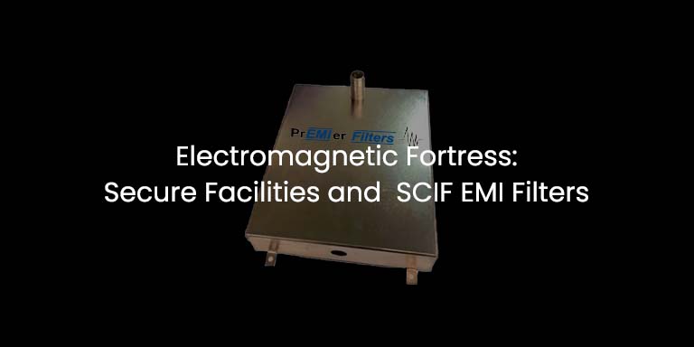
Electromagnetic Fortress: Secure Facilities and SCIF EMI Filters

Electromagnetic Fortress: Secure Facilities and SCIF EMI Filters

Electromagnetic interference (EMI) can pose significant threats to the operation and security of sensitive electronic equipment in secure facilities. These facilities, which include data centers, military installations, and research laboratories, house critical infrastructure and valuable information that need to be protected from external and internal EMI sources. EMI filters play a vital role in maintaining the integrity of these facilities and ensuring that sensitive electronic systems remain operational and secure.

Understanding EMI Filters

EMI filters EMI filters are designed to prevent the ingress or egress of electromagnetic radiation to and from electronic devices and systems. They are composed of passive electronic components, such as inductors, capacitors, and resistors, that are specifically arranged to suppress or attenuate unwanted electromagnetic signals. By filtering out EMI, these devices ensure that sensitive electronic equipment operates as intended without being disrupted by external electromagnetic noise .

Applications of EMI Filters in Secure Facilities

  • Data Protection: EMI filters can help protect secure facilities from data theft and cyber-espionage by preventing the unintentional leakage of electromagnetic signals. These signals, known as compromising emanations or “TEMPEST,” can be intercepted and decoded by malicious actors to access sensitive information. By installing EMI filters on communication lines and power supply systems, facilities can minimize the risk of data leakage.
  • Equipment Reliability: In secure facilities, the smooth operation of electronic systems is paramount. EMI filters help maintain the reliability and performance of these systems by shielding them from external sources of electromagnetic noise, such as radio frequency (RF) signals, power line disturbances, and other nearby electronic devices.
  • Interference Reduction: In some cases, sensitive electronic equipment within a secure facility can generate EMI that interferes with other devices in the same environment. EMI filters can be employed to mitigate this issue, ensuring that all systems within the facility operate harmoniously and without interference.
  • EMP and HEMP Protection: Electromagnetic pulse (EMP) and high-altitude electromagnetic pulse (HEMP) events can cause severe damage to electronic systems. By integrating EMI filters with other shielding techniques, such as Faraday cages and shielded enclosures, secure facilities can enhance their resilience to these potentially devastating events

Conclusion

EMI filters are a critical component of the defense strategy for secure facilities, protecting sensitive electronic systems from both internal and external sources of electromagnetic interference. By investing in EMI filters and incorporating them into the design and operation of secure facilities, organizations can ensure that their critical infrastructure and valuable information remain protected from the ever-evolving threats posed by EMI.

If you’re looking to learn more about how Premier Filters has the solution for you, contact us at info@premieremc.com or +1-657-226-0091.

Ways to Reduce Power-Supply Noise

Ways to Reduce Power-Supply Noise

Noise is undesired harmonic energy resulting from fast changes in voltage and current in electronic equipment and circuits. In a power supply, this is primarily caused by the high frequency power conversion switching circuits (e.g. PWM). This noise can conduct onto and radiate from PCB traces and wires and cables. Several common practices can be employed to reduce the noise so it does not propagate into other equipment and systems.

Filtering

EMI Filters utilizing inductors and capacitors can be used at the input and output ports of the power supply. Filtering at the input is governed by international EMI standards that limit the noise that can be propagated onto the power supply network. Output filtering typically is done to reduce radiation from the output circuits and cabling feeding the various loads of the power supply.

Bypassing

Bypassing is the simplest form of filtering, where capacitors are used to reduce circuit noise, specifically that related to the supply and return pins. To increase the bandwidth effectivity of the capacitors, SMD and ceramic capacitors are used. Placement near the noise source as well as reducing impedance from long leads/trace circuits is critical.

Reducing Inductance and Circuit Loops

Trace inductance and circuit loop control are inter-related. Utilization of power and ground planes can go a long way to reducing radiation and coupling from circuit loops.

Decoupling

Decoupling is similar to bypassing in which a circuit is isolated from the noise of another circuit. It will reduce the amount of supply trace shared between circuits.

Decoupling consists of a high impedance element along the supply line to ensure that the current noise will flow through the low impedance bypass element. It will act as a low pass filter so that the high-frequency content of any current that does pass through the series element will be reduced.

If you’re looking to learn more about how Premier Filters has the solution for you, contact us at info@premieremc.com or +1-657-226-0091.

Where Can EMI/RFI Come From

Where Can EMI/RFI Come From

Electromagnetic Interference (EMI) and Radio Frequency Interference (RFI) are two sides of the same phenomenon in which electronic devices produce and are affected by electromagnetic radiation. The terms RFI and EMI are frequently used interchangeably as radio waves are merely a subset of the electromagnetic spectrum.

EMI/RFI are becoming more of a problem in today’s world. Signals from radio, cell phone, and Wi-Fi transmitters fill the air. In addition, radio wave noise is also produced by solar activity and other sources from space. Furthermore, as devices get smaller, they become more susceptible to EMI, especially when the distance between circuits is less than one wavelength.

Where can EMI come from?

The sources of EMI can be both natural and man-made. Almost any electrical source has the potential to disrupt the electrical components of a product in its neighborhood, though the degree of disruption varies greatly.

Natural Causes:

Natural causes of emi

– Lightning

– Solar flares and radiation

– Dust and snow storms

– Electrical storms in the atmosphere (the cause of the Northern and Southern Lights)


Man-Made Causes:


Industrial:

man made causes of emi

– Electric motors and generators

– Power supplies

– Cellular networks

– Transmitters

– Transformers


Home Goods:

– Electric blankets

– Electric bug killers

– Baby monitors

– Microwaves

– Heaters

– Lamps

– Wi-Fi and Bluetooth devices


Filtering

Many EMI filters allow only certain frequencies to pass through, implying that a specific range of EMI/RFI emissions will be transmitted to the device being protected. This is because certain EMI/RFI emissions, within a certain range, will not interfere with the performance frequencies of various electric and electronic devices. Cable televisions, for example, operate at different frequencies than radio waves, ensuring that they do not interfere with one another. The primary frequency pass settings are as follows:

1. Low Pass filters allow low-level frequencies below a certain cutoff point to pass through.

2. High Pass filters allow high-level frequencies above a certain cutoff point to pass through.

3. Band Pass filters allow frequencies within a specific frequency range to pass through.

4. Band Stop or Band Reject filters allow frequencies outside of a specific frequency range to pass through.

Shielding

emi shielding

When an electromagnetic wave passes through a conductive material, its energy is reduced or “attenuated.” A layer of conductive material serves as EMI shielding. It may be intended to protect a device from its surroundings or to protect device components from one another.

Metal enclosures provide excellent EMI shielding. However, many modern enclosures are made of plastic and provide no inherent protection. EMC is commonly achieved by coating the inner surfaces of plastic enclosures with conductive paint.

Attenuation effectiveness of a shield is measured in decibels (dB). Attenuation of 10 dB shielding reduces the incident wave’s energy by a factor of ten. 20 dB reduces it by a factor of 100; 30 dB by a factor of 1000, and so on.

It is important to note that the shielding effectiveness of all materials varies with the wavelength of the radiation being shielded.

What is Low-Pass Filter

What is Low-Pass Filter

A filter that passes frequencies below a certain frequency and blocks signals above this frequency is known as a low-pass filter. The point where this occurs is called the cut-off frequency and is typically the point where the frequency response drops -3dB from the passband.

Ideally, the frequency response drops at the cut-off frequency, but practically the frequency response curve will gradually decrease from the transition region to the stopband region. The transition region is the area where falloff occurs. The stopband region is the region where the attenuation occurs.

Low-pass filters can be passive or active. A passive low-pass filter uses only passive components (e.g., resistor, capacitor, inductor). An active low-pass filter uses active components (e.g., transistor, op-amp, FET, etc.) along with passive components. In comparison to a passive low-pass filter, an active low-pass filter is more effective but may be limited in bandwidth.

A simple circuit of an active low-pass filter uses an operational amplifier. In this filter, the high impedance signal acts as an input and provides a low impedance signal as an output. The op-amp is used in the circuit to increase the amplitude of the output signal. The op-amp is also used to make the output signal wider or narrower. The amplifier used in the circuit design determines the maximum frequency response of the filter.

low pass filter

The above diagram shows a simple circuit design of an active low pass filter. At low input frequencies, signals directly pass through the op-amp (or the amplifying circuit). For high input frequencies, the signals pass through capacitor C1. This filter circuit increases the output signal amplitude by the passband gain of the filter. For a non-inverting amplifier circuit, the magnitude of the voltage gain can be obtained using the following formula:

Vout = {1 + (R2/R3)}

Low pass filters are used in a plethora of equipment and systems. These include telephone systems, receivers, multi-rate DSP and as power line filters to meet conducted emission requirements. At Premier Filters, we bring over 35 years of design experience and knowledge to make sure the right filter is designed. With a full range of AC and DC power line filters and unlimited custom capability, Premier delivers the right filter on time and on budget. To know more about our EMI filter solutions, email us at info@premieremc.com.

EMI Filters: Working Principles and Types

EMI Filters: Working Principles and Types

The abbreviation EMI means Electromagnetic Interference which is a disturbance caused to one electrical device by another electrical device. This happens either via direct or indirect contact. Direct contact is called conducted EMI and indirect or non-contact induction is called radiated EMI.

An EMI filter is a device that is used as a protection shield from EMI. The EMI filter is either present in the circuit board of the electrical device or it is presented separately. Whether  the EMI filter is a segregated device or embedded into the circuit, it will be a part of every electronic device. In general, low pass filters make up the bulk of EMI filters used in electronic devices. These filters will pass low frequency signals, such as 60hz power, and attenuate higher frequencies. In general, an EMI filter provides filtering over a broad range of frequencies with the upper range extending into the high MHZ frequencies. This is primarily achieved through the use of passive components, such as capacitors and inductors.

The position and location of the EMI filter in a device plays an important role in the filter achieving maximum performance. A filter should be located as close as possible to the noise generating circuits and at cable and wire egress points. The latter is to maintain the overall isolation and shielding performance of the host metal cabinet. This also requires that the filter metal housing be properly bonded to the host cabinet. Non-conductive surfaces are to be avoided in which the filter housing is to be metal-metal bonded to the host cabinet.

Types of EMI Filters

EMI filters are classified into two types, passive and active EMI Filters, in which passive filtering finds the greatest application and use.

Passive EMI filters consist of inductors and capacitors arranged in specific circuits to achieve the desired filtering. A filter’s performance is dependent upon the host circuit’s source and load impedances and is critical to understand if the filter is to achieve its intended performance. Additional considerations include capacitor lead layout, placement of components to minimize cross coupling and near field radiation effects and proper selection of the magnetic core material to use in the inductors.

 Active filters are thus named as they use active circuits (e.g. op-amps) in conjunction with passive components to achieve the desired filtering.  Types of Active EMI filters include Current Sensing Voltage cancellation (CSVC), Voltage-Sensing Voltage-cancellation (VSVC), Current- Sensing Current Cancellation(CSCC), & Voltage-Sensing Current cancellation(VSCC). Active filters tend to play a greater role in low level circuits as compared to higher  voltage/current input AC power circuits and can be limited in bandwidth effectivity relative to passive filters.

What is EMI Shielding and Why is it Important for Your Design?

What is EMI Shielding and Why is it Important for Your Design?

An EMI shield is a metal housing or structure that blocks electromagnetic fields from radiating and coupling into other circuits and systems. EMI shields protect electrical/electronic devices from external radiation that can interfere with sensitive circuits and cause operation failures, loss of data and system malfunctions.

EMI shielding can come in many forms and metal compositions. Common types are box structures, gaskets, plates, conduits, honeycomb vents and braids. The most common materials are steel, aluminum and copper. However, specialty materials can be used in severe low frequency magnetic environments. Gaskets are used to bridge metal surfaces, such as lids on a housing or cabinet. This is to ensure continuous metal-metal contact across the entire length of the seam. Typical materials are metal mesh, conductive elastomer and beryllium copper. Braids are used for cable and wire shielding and are usually composed of plated steel or copper. Honeycomb vents provide superior shielding for cabinet access and air ventilation apertures and are designed as waveguides beyond cutoff.

Identifying the right shield for a specific equipment requires an in-depth knowledge of materials, end use environment and the culprit noise generators. help to decide which EMI shielding is best for your application environment. For this, you can contact the experts of Premier Filters – the designer and manufacturer of AC/DC EMI filters. Our high-quality products are used in different application environments such as military, commercial and industrial applications. Our in-house engineering and design expertise provide custom EMI solution to ensure that your equipment is catering to the industry-standard requirements.

At Premier Filters, we bring over 35 years of design experience and knowledge in EMI/EMC. We can assist in defining an equipment’s shield design to support compliance to international standards.  Coupled with our full range of AC and DC power line filters and unlimited custom capability, Premier delivers the right solution on time and on budget. To know more about our EMI filter solutions, email us at info@premieremc.com.

Electromagnetic Compatibility in the Smart Grid Environment

Electromagnetic Compatibility in the Smart Grid Environment

For continuous reliable real-time operation in areas where Smart Grid equipment will operate, one must consider the surrounding EMC environment. The components and devices of the Smart Grid system are subjected to a wide range of noise sources that can disrupt all electronic systems, including the smart grid systems. These noise sources can be conducted or radiated and can occur from various sources, as follows:

1. Power line harmonics

2. Fast transient or bursts

3. Surge from lightning and power system switching transients.

4. Transmitters (such as AM, FM, and TV broadcast transmitters, communications radios, and wireless devices),

5. High power events from portable transmitters, geomagnetic storms, and EM pulses associated with high altitude nuclear detonation (HEMP).

6. Electrostatic discharge events.

With the steady growth and changes to Smart Grid technology, it is necessary to make a dynamic strategy that will help in maintaining EMC and reliable operation. In the Smart Grid, from manufacturers to customers, everybody plays a crucial role in maintaining a robust and reliable grid control system.

Manufacturers

They are responsible for designing and testing products to demonstrate EM immunity per specific standards.

Utilities

They specify that components for the smart grid meet the EMC requirements in the specific standards and may require additional compliance testing.

Electric Power Customers (Commercial and Industrial)

Must follow good installation procedures and specify products that have good EMC design.

SDOs

They develop and update EMC standards (wherever required) for reflecting the progress in technology and the Smart Grid electromagnetic environments.

Government

The government evaluates the national policies and priorities for protecting the electric power infrastructure from electromagnetic interference (especially high-power events like HEMP and geomagnetic storms.

Bottom Line

To assure reliability, EMC must be designed into all devices which compromise the Smart Grid control system. All Smart Grid devices cannot tolerate all EMC environments. However, if EMC is not considered, the probability of the system failing to operate as intended increases significantly. Good design practices along with an extensive test program will significantly increase the probability that the Smart Grid system will work and withstand the disturbances caused by the electromagnetic environment.

At Premier Filters, we bring over 35 years of design experience and knowledge to make sure the right filter is designed. With a full range of AC and DC power line filters and unlimited custom capability, Premier delivers the right filter on time and on budget. To know more about our EMI filter solutions, email us at info@premieremc.com.

PCB Design Guidelines for EMI/EMC

PCB Design Guidelines for EMI/EMC

In this blog post, we present some general PCB (Printed Circuit Board) design rules. Although, PCB design can have the greatest impact on radiated noise, it also helps to control coupling of noise to the power cord and reduces common-mode coupling of noise to the ground or chassis. The following lists some basic considerations in PCB EMI/EMC design.

PCB Trace Considerations

  • Keep signals (audio, video, clocks, etc.) separate from power and other traces. This helps to minimize crosstalk and coupling between adjacent traces on the same PCB layer.
  • Bend traces at 45⁰. 90⁰ bends increases impedance due to the sharp corners and can increase radiation.
  • Route high-speed signals via differential pairs.
  • Utilize decoupling capacitors on all power traces and planes.


Ground Planes

  • Utilize separate ground planes/layers for all power and signal returns. Separate layers increase the overall surface area reducing HF impedance effects, as well as reducing circuit loop areas.
  • Avoid long return paths and large loop areas.
  • Physically isolate noisy circuits from sensitive ones.
  • Keep high-speed circuits near the ground plane while low-speed circuits near the power plane.
  • Separate or segregate multiple power supplies by a ground plane.
  • Be careful with split apertures that are long holes and wide vias in the power plane and the ground plane. Split apertures create a non-uniform area due to which the impedance increases in the power plane and the ground plane.


Shielding

  • EMI/EMC shields can protect signal circuits from external noise. These can be small metal housings connected to ground planes for shielding entire circuits or individual noise emitters, such as clocks.
  • Shield signal cables to prevent noise coupling and signal degradation.


PCB Layers

  • Utilize multi-layer boards with separate ground and power planes.
  • If separate power planes are not used, then route ground traces in parallel with power traces.
  • For four or more layers, alternate signal and ground layers. Make sure the number of layers is even.


Decoupling Capacitor

  • Integrated circuits (ICs) switch current at high-frequency due to which switching noise occurs in the power traces or power rails (connected to the IC). If this noise is not controlled, it will result in radiated emissions, and hence, EMI will occur. Therefore, to reduce the power rail noise, place the decoupling capacitors near the IC power pins, ground the capacitors directly to the ground planes, or replace power traces with power planes.


Control Impedance for Transmission Line Design

  • Circuits operating at high-speed require impedance matching between the source and destination circuit. If not controlled properly signal reflection and high-frequency ringing can occur resulting in excess RF energy which can radiate or couple to other circuits.


Conclusion

The PCB design of an equipment affects the EMC performance and the amount of EMI generated. With good PCB design practices the overall noise required for filtering can be minimized.

At Premier Filters, we bring over 35 years of design experience and knowledge to make sure the right filter is designed. With a full range of AC and DC power line filters and unlimited custom capability, Premier delivers the right filter on time and on budget. To know more about our EMI filter solutions, email us at info@premieremc.com.

EMI Filter Installation Best Practices

EMI Filter Installation Best Practices

EMI (Electromagnetic Interference) filters are a necessary component for most types of systems or equipment as it enables proper operation without interference to or from other systems. A key parameter to maintaining EMI filter performance is proper installation. Grounding/bonding, wiring, and mounting each play an important role in achieving maximum filter effectiveness.

Grounding/Bonding

EMI filters are to be properly grounded/bonded to the host equipment to achieve optimum performance and meet safety requirements. The main factors to consider are as follows:

Grounding Bonding

  • Ensure filter housing is bonded to host cabinet via metal-metal connection. All surfaces are to be conductive and void of paint or other insulating material.
  • For non-metal housings and/or cabinets, the filter is primarily grounded via the incoming safety wire. Make sure this wire is as short as possible upon entry into the host equipment. In addition, any connections to cabinet metal frame elements are to be made with flat braid instead of wires. This will help to achieve a low impedance ground/bond at high frequencies.
  • As redundant safety wire connections are often required in addition to the metal-metal bonding of the filter housing to the host cabinet, make sure that the ground connections are as short as possible. Use a flat braided ground strap, if required, as it provides increased surface area.


Filter Wiring and Cable Layout

Proper control of wires and cables is essential in maintaining the performance of an EMI filter by reducing alternate noise paths. A few key considerations are as follows:

  • Maintain physical isolation and separation between filter input and output wires. Make sure filter output wires are not routed close to or next to the input wires.
  • Make sure to keep power wiring separate from control wiring. Power and control wires must not run in parallel. Keep control wires away from the incoming power lines to the filter.
  • Route wires next to the host cabinet’s metal surfaces. This will help to decouple noise from the wires.
  • If necessary, use shielded wiring to protect the filter input wires from radiated noise and terminate both ends of the shield of shielded cables.


 EMI Filter Mounting

An EMI filter’s performance is also dependent on proper mounting, as follows:

  • Locate the filter as close as possible to the entry point of the input power wires.
  • For optimum performance, bulkhead mount the filter to the host cabinet. This will eliminate any required input wiring into the system.
  • In case bulkhead mounting is not possible, make the input wires or cables are as short as possible and if required, shield them.
  • Depending on the system, additional filters may be required where the EMI sources are located.
  • Place cables away from the known sources of noise in the system.
  • Mount the filter directly to the host cabinet metal surface. Make sure all mating/bonding surface are conductive.


Wrapping up

Implementation of proper installation techniques ensures an EMI filter will perform as designed. At Premier Filters, we bring over 35 years of design experience and knowledge to make sure the right filter is designed and properly installed. With a full range of AC and DC power line filters and unlimited custom capability, Premier delivers the right filter on time and on budget. To know more about our EMI filter solutions, email us at info@premieremc.com.

Process for Selecting an EMI Filter

Process for Selecting an EMI Filter

Modern-day electrical and electronic devices utilize HF (high-frequency) switching circuits that generate HF harmonics that can propagate via cables or air. This high-frequency noise is known as EMI (electromagnetic interference) which can cause disturbance or malfunction to nearby equipment and electronic systems.

In reducing EMI that propagates via cables, EMI filters can be an effective tool in suppressing unwanted high-frequency signals. EMI filters serve a dual function, reducing noise from outside sources as well as internally generated noise. They are especially effective in reducing noise from supply and equipment power lines. In designing a filter there are several criteria to consider. A few of these are presented below.

How to Select the Right EMI Filter?


1. Review Electrical and Operational Requirements

The first step to designing an EMI filter is to review the specification and system requirements. This includes parameters such as voltage, current, operating and/or ambient temperature, dielectric withstand or hipot voltage, leakage current and power system feed/type. These ratings are usually provided as max ratings which the filter can accommodate without degradation of performance or reliability. This means that the filter can operate at any ratings up to and including the max ratings.

Typically, EMI power line filters are rated for 250VAC and 480VAC for single and three phase systems. DC ratings can range from 28VDC to 1500VDC for solar applications. Single phase EMI filters are generally rated for a 40C ambient temperature and 50-60C for three phase. Leakage current ratings are usually dictated by the end use environment. Domestic environments are can be specified as low as 500uA with medical installations being as stringent as no leakage current for patient connected equipment. Industrial applications are less stringent and can range from 3.5mA to 30mA or higher.

2. Analyze Application and System Requirements

Equipment Type
The selection of EMI filters depends on the type of equipment and its components, such as AC/DC converters, industrial equipment, medical equipment, RF modules, etc. An EMI filter used in one application may not necessarily work for other applications because of unique performance, space, and interconnection requirements. The characteristics of electronics equipment, such as clock frequencies and switching frequencies, affect the emission profile of EMI filters.

Industry Requirements
Different industries have established emissions and safety standards that the equipment must comply with. For instance, MIL-STD-461 is a military standard that governs military application requirements. Thus, before selecting the right EMI filter for your application, keep in mind the industry requirements.

Filter Type
Some filter designs may be more desirable for an application than others, for instance, PCB or power line filters. Therefore, you must thoroughly research the available filter types and consider the one that will work best for your application.

Size Restrictions
It is important to understand spatial limitations early in the design stage. Standard filters can come in various sizes, performance levels, interconnection, and mounting configurations. Limitations in standard designs can be resolved via modified or custom solutions.

Terminations
Filters can have different terminations, such as studs, wires, connectors, and fast-on/quick disconnects, in which proper selection is important for performance and reliability.

Grounding/bonding
It is essential for the safety and high-frequency performance of the filter that the filter chassis be metal-metal bonded with the host equipment.

3. Review Actual EMI Filtering Characteristics

Filter datasheets generally display performance in the form of insertion loss tables/graphs. These are separated into common (referenced to ground) and differential (referenced across the line) mode types and are measured as ratios of the signal at the filter input to the signal at the filter output in decibels (dB) relative to 50 ohm source and load impedances. As actual system impedances may differ, testing is critical in determining the actual performance of a filter.

4. Preliminary EMC Testing

Preliminary or precompliance testing of a device can be very effective in determining early on the selection of an EMI filter. The test results can then be compared to insertion loss graphs of various EMI filters to determine the proper filter for the defined space and performance levels.
Standard and Custom Solution by Premier Filters

The above guidelines for selecting an EMI filter is just a baseline and does not cover every possible aspect. At Premier Filters we can help you select the proper standard filter, or when necessary, design a custom solution. Contact our engineering team at 714-809-1004 to discuss your custom EMI Power Line Filter application or email us at info@premieremc.com.

EMI And EMC Testing: What Is It And Why Is It Necessary?

EMI And EMC Testing: What Is It And Why Is It Necessary?


EMI and EMC

EMI (Electromagnetic Interference) can disrupt the operation of an electronic device that is placed close to the electromagnetic energy of an external electrical source (natural or man-made). Disruption may cause the failure of the device, or the device may not be able to function properly.

EMI sources can be natural or man-made. Natural sources include solar radiation, electrical storms, etc., while man-made sources include devices such as switch-mode power supplies, personal computers, solar inverters, etc.

EMC (Electromagnetic Compatibility) pertains to enabling a device to function properly in its intended environment in the presence of EMI sources.

EMI and EMC Testing

Testing is essential to determine that a device can operate within its intended environment and in accordance with required standards. Pre-compliance and compliance testing are generally  performed by specialized test facilities or test houses, although many companies have incorporated some level of pre-compliance test capability in-house. Compliance testing for EMI/EMC requires methods, equipment, and measurement sites in compliance with national or international standards. Individual nations define compliance with national and international standards that may vary.

EMI and EMC testing can be categorized into the following categories:

  • Emissions Testing
  • Immunity Testing


Emissions Testing

Emissions testing measures the amount of electromagnetic noise generated by the device. The purpose of emissions testing is to ensure that emissions from the device are below the defined limits to ensure that the device will not cause any harmful interference to other devices operating within its expected operating environment.

Immunity Testing

When a device is exposed to electromagnetic noise and other disturbances, immunity testing measures its reaction. The purpose of immunity testing is to assure that the device will perform the desired operation when used within its expected operating environment.

Why is EMI and EMC Testing Necessary?

Designers and manufacturers of electronic products must care about EMC compliance. Countries across the world have defined EMI and EMC regulations to improve reliability and safety to their electrical and electronic equipment users. The regulatory bodies have set specific limits on the amount of unwanted emission emitted from a device. The primary goal of such limitations is to prevent interference to nearby TV or radio receivers. If an electrical/electronic product fails to pass EMI/EMC regulations, it may result in fines, seizures or product recalls.

EMI Testing With Premier Filters

Premier Filters conducted emission pre-compliance test capability can evaluate products to determine a system’s filtering needs before paying for independent testing at an EMI/EMC lab. With 70+ years of EMI/EMC experience, Premier can define and provide the right filter ahead of schedule and under budget. For further information, visit https://www.premieremc.com.

Comparison of Active and Passive EMI Filters

Comparison of Active and Passive EMI Filters

When a product is unable to pass EMC certification due to some mysterious EMI source, the manufacturer will probably start redesigning the product by rearranging the components. However, there may be more ways to suppress specific sources of EMI. The manufacturer can use a variety of EMI filters to suppress EMI in different frequency ranges.

EMI filters are of two types: passive and active. Both types of filters provide different levels of suppression in different bandwidths. An EMI filter design is based on various factors, such as space on the circuit board and required attenuation.

Passive EMI Filters

Passive EMI filters consist of inductive and capacitive elements that filter over a wide frequency range. Compared to active filters, a passive EMI filter consumes less power, has lower-cost components and when cascaded provides multi-band filtration. Filtering behavior can be easily predicted using basic series and parallel impedance equations.

Another commonly used passive element is the ferrite bead or coke. This inductor passes lower frequencies and is commonly used on cable and wires to filter out high frequency radiated noise. The power cord of a laptop uses one of these chokes to remove high-frequency noise on the input power line.

The simplest type of passive EMI filters are L and C filters. These filters can be placed in any critical circuit or on the input of any critical component to remove noise at a broad range of frequencies. There are more complex configurations of passive EMI filters – LC filter, CL filter, T – filter, and Pi filter. Out of these configurations, Pi and T- filters are best used with low and high-source or load impedances, respectively.

Passive filters are designed according to circuit requirements. If there is a need to pass the desired signal into a component, then a bandpass filter is built. In case a strong signal is to be suppressed at a single frequency, then the bandstop filter will be needed. The number of passive elements (L or C) in the circuit indicates the filter number. A higher-order filter (i.e., cascaded filter) will provide steeper roll-off outside the passband.

Active EMI Filters

Complex filter circuits include op-amps that provide linear or non-linear broadband filtering. However, the active components can be a limiting factor in governing the EMI suppression as these components have some well-defined bandwidth.

Active filters are designed using operational amplifiers (op-amp) or more complex circuitry. These filters can be easily configured as higher-order filters for common-mode and differential-mode noise. It’s a simple way to remove near-field EMI in the design using discrete components with a small footprint.

A circuit that suppresses common-mode and differential-mode noise over a broad bandwidth can be built using an op-amp along with some capacitors and resistors. Such a design is easy to analyze. At ultra-high frequencies (microwave and mmWave frequencies), parasitics in the circuit board and components become critical. Passive elements will stop showing ideal behavior due to self-resonance, capacitors will start to exhibit inductive impedance, and inductors will exhibit capacitive impedance. Ensure to check the self-resonance frequencies of components while designing EMI filters in order to remove the strong high-frequency noise from specific sources.

Mechanism of Causing Electromagnetic Noise

Mechanism of Causing Electromagnetic Noise

Electromagnetic Interference (popularly known as EMI) is an electromagnetic/electrical disturbance that causes the malfunctioning or degradation of electrical equipment. It can not only lead to the loss of transmitted data, but it can also damage the equipment completely.

Despite all the disruptions caused due to EMI, it is common in the modern environment. EMI occurs due to natural causes as well as man-made electrical devices. Man-made EMI results due to electrical/electronic circuits, switching systems, or changes in large amounts of current. Man-made EMI occurs in both the residential and industrial sectors.

1. Natural Causes

A variety of sources that lead to natural causes of EMI are the sun, dust storms, lightning strikes, snowstorms, solar flares, static electricity, solar magnetic storms, cosmic noise, and atmospheric electrical storms.

The sudden occurrence of natural EMI creates a severe impact on inadequately protected electrical devices. For instance, atmospheric electrical storms or solar flares affect military equipment or transportation technologies. The sun disrupts satellite transmissions if it appears right behind the satellite, and the EMI blocks the satellite transmission. Snowstorms disrupt cell phone signals or cause radio static.

2. Man-made Residential Causes

Man-made residential causes of EMI emanate due to electronic devices and appliances. Although it does not inflict permanent or severe damage, it causes disturbance to other devices in the home and leads to the poor performance of electronic devices.

A variety of sources that lead to man-made residential causes of EMI are lamps, heaters, cell phones, Bluetooth devices, wi-fi devices, heating pads, toaster ovens, microwaves, electric blankets, baby monitors, treadmills, solar inverters, etc..

The impact of residential sources of EMI increases with the increase in the usage of electronic devices. Increasing the usage of mobile phones and computers has increased the density of electromagnetic currents in the environment. People often use these devices continuously and in closer proximity, and thus, these devices are more likely to cause electromagnetic interference.

The improvement in the performance of electronic devices increases the EMI occurrence. Electronic devices are expected to have high performance. For improved performance, devices operate on a high frequency that produce electromagnetic noise across a broad range of frequencies.

3. Man-made Industrial Causes

Industrial causes of EMI often occur large-scale and can cause severe interference with essential technologies. A variety of sources that lead to man-made industrial causes of EMI are:

  • Medical equipment: In the medical industry, technologies like X-ray machines, MRIs, telemetry units, electrical surgical units, and other equipment produce EMI which can interfere with other medical technology.
  • Grid power: The electrical grid often has high voltage and low-frequency transmission lines that can disrupt certain electronic devices. Disruptions in power grid include voltage surge, voltage spikes or dips, and blackouts and brownouts that can also result in electromagnetic interference in devices/equipment connected to the power grid.
  • Radio and satellite: Radio waves and satellite waves transmitted worldwide can cause EMI with cellular networks or sensitive equipment.
  • Electric motors and generators: They can produce a large amount of high-frequency noise and high voltage transient spike.
  • Television transmissions: TV transmissions can cause EMI to residential and industrial devices.
  • Cellular networks and telephone transmissions: Wire as well as wireless telecommunication produce EMI. With the increase in the cellular grid, the number of cell phone users increases, and hence the noise from cell networks become a more severe threat to other electronic devices.
  • Railroads and mass transportation systems: Trains and mass transportation systems produce EMI from their propulsion system, control system, signaling system, and other processes. Such systems operate at high voltage and current that can affect components of other transportation systems or electrical devices in facilities located near railroads.
  • Other high-frequency sources of EMI: In many industrial processes, components like transmitters, inverters, transformers, microprocessors, and controllers produce high-frequency EMI.


Industrial causes of EMI can not only affect technologies within the same facility but also cause more widespread disruptions.

EMI Filtering for High-Reliability Applications

EMI Filtering for High-Reliability Applications

Signal transmission and integrity can be disrupted by electrical noise, or Electromagnetic Interference (EMI). This noise can be caused by natural and man-made sources. The primary area of concern is man-made noise created by high frequency switching circuits used to transform power and generate digital or logic and clock signals. An invaluable tool to reduce EMI and improve signal and circuit operational reliability is the implementation of EMI suppression filters. These filters primarily consist of passive elements such as inductors, capacitors, resistors, ferrite beads and transient suppressors.

Power line and signal filtering is required for all types of equipment and systems, such as military, commercial, industrial, laboratory and medical. EMI Power Line Filters are especially critical as they suppress noise from propagating out onto the power distribution system. They provide additional challenges as they are a safety critical item in which most environments require limitations on leakage current.

Medical devices require several design considerations especially for patient contact equipment. Stringent leakage current levels limit the line to ground capacitance that can be used placing greater importance on a filter’s inductive design. In addition, proper PCB layering, layout and bypass filtering is required to limit radiated noise that can couple into other equipment and their sensitive circuits. To ensure patient safety, global regulatory bodies impose strict limits on manufacturers and suppliers of medical devices which require the use of EMI filters that comply with these regulations.

Medical devices require several design considerations

As with medical devices, products manufactured for aerospace and defense are required to comply with strict rules and regulations that govern all aspects of device performance, manufacturing, and testing. This is to ensure operation in severe environments and under HEMP/EMP threats. Governing standards include DO-160 and Mil-STD-461.

Regulations for commercial filters can vary worldwide, but for most countries they have been harmonized to the applicable CISPR and IEC standards. Power line conducted emission limits are specified for the frequency range 150Khz to 30Mhz. EMI Power Line Filters are required to meet these limits and can take the form of on-board discrete components or a single metal encased filter. Due to the frequency range, noise is primarily dominated by common-mode propagation, where aerospace and military specify a lower frequency of 10Khz, requiring both differential and common mode design.

Conclusion:

In conclusion, High-reliability electronic devices have challenging requirements that require increasingly complex EMI filtering. EMI noise levels and safety criteria are dictated by international standards that ensure a filter’s performance and reliability when designed into today’s sensitive electronic devices.

The History of Radio Frequency Interference and Causes

The History of Radio Frequency Interference and Causes

Radio frequency interference, commonly known as RFI, is a term that harkens back to the onset of telegraph lines and radio towers. Today, RFI is encompassed by the much broader term of EMI (Electromagnetic Interference). Since the invention of the transistor, electronic devices have incorporated high frequency switching techniques to transform power and enter in the digital age. Today, this technology is used in almost every device that can be found in our homes, offices, cars and airplanes.

With the digital age comes greater sensitivity of circuit operation to externally generated RF or EMI noise. These circuits can operate at millivolt and microvolt levels making them vulnerable to even low levels of induced noise. Have you ever wondered why you need to shut off your mobile phones when the plane takes off or lands? Or why your car radio produces a buzzing sound just before your mobile phone rings? It is because electronic devices that operate within the crowded landscape of frequencies interfere with each other.

The presence of unwanted signals or noise generated by power and digital fast switching circuits is increasing at a rapid rate. This noise can conduct down power lines as well as radiate from power and signal lines and couple into other equipment. Military and commercial standards have been created to establish noise limits that an equipment can conduct and radiate. The test frequency range is very broad and is primarily concerned from 10Khz to 10Ghz.

In the design of electronic products, EMI or RF interference must be addressed at each stage of product development. From initial analysis to board layouts and circuit topology and ICs used. Therefore, determining compliance and defining the techniques and materials to be used to mitigate an equipment’s emissions and susceptibility vulnerability is critical. In general, two of the more prominent techniques involve the use of shielding and filtering.

rf shielding

RF shielding incorporates the use of metals to reflect and/or absorb radiated noise so that it does not radiate into the surrounding environment. In addition to the metal used for the chassis or box design, bonding, penetrations and openings must be designed in order to maintain the overall shield integrity. Additional techniques include PCB design, cable routing and shielding, grounding and circuit compartmentalization.

The use of EMI filters is critical in controlling noise generated within a PCB and at equipment power and signal egress points. The majority of designs incorporate passive techniques using capacitors and inductors. These components are designed to provide mismatched circuit impedances to contain noise voltages and currents within an equipment or system so that they do not propagate into the external environment.

What is RF Interference?

What is RF Interference?

RF Interference (RFI) or EMI (Electromagnetic Interference) is an invisible phenomenom that is all around us. In general, it is created by sharp changes in circuit voltage and current (di/dt, dv/dt). Lines across an older TV when you operate a vacuum cleaner, a blown LED light when the AC turns on, or an AM radio being drowned out when using a treadmill are all examples of RF Interference. RF stands for Radio Frequency and RFI was originally used to describe interference caused by radio transmissions. As electronics and technology have progressed, RFI has been replaced by the broader term EMI.

The issues related to RF interference are increasing daily with the usage of mobile phones and other consumer electronics, residential solar inverters, smart appliances and the continual proliferation of high frequency switching for power conversion. In the design and manufacture of electronic products, RF interference control plays a critical factor in each stage of product development. There are many criteria associated with achieving proper RF interference control in an equipment. Three key factors are shielding, PCB design and filtering.

1. Shielding


Shielding is the use of metals such as copper, aluminum and steel to contain RF Interference

Shielding is the use of metals such as copper, aluminum and steel to contain RF Interference at the equipment level, to shield sensitive circuits or for targeted radiation control. Proper application is needed to achieve the desired performance. Metal to metal bonding, metal type and thickness, ventilation design, cable design, lid/seam design, etc. are all factors that need to be considered. Regarding cable shields, proper termination is critical, with 360 degree terminations being optimal. Depending on frequency, the use of shield drain wires can be used. However, the longer the drain wire, the greater chance of shield degradation.

2. PCB Design


PCB design is critical in controlling radiation from logic and control circuits

PCB design is critical in controlling radiation from logic and control circuits. Implementation of bypass filtering, circuit loop control and multi-layer boards are just some of the techniques used by designers to control and reduce radiation form logic boards.

3. Filtering

The use of filtering to reduce RF Interference plays a key role in conducted, as well as radiated emission control. Power line filters, cable and I/O filters installed at an equipment’s point of egress are critical to controlling noise from propagating into other electronic equipment. Filter location, case design, bonding, cable routing, etc. are just some of the factors to consider to achieve optimum filter performance.

In summary, RF Interference control and mitigation plays a critical role in equipment design. At Premier Filters, we address all aspects of an equipment’s RFI/EMI design to deliver the right filter at the right price.

Difference between EMI and EMC

Difference between EMI and EMC

Electromagnetic interference (EMI) and Electromagnetic Compatibility (EMC) represent two sides of the same coin. EMI is emitted, transmitted, conducted or radiated noise from electronic equipment and systems, while EMC is the ability of electronic equipment and systems to function or operate, without upset or failure, in the presence of EMI.

All electronic devices or equipment produce conducted and radiated electromagnetic noise. This noise is unintended and due to harmonics created by today’s power conversion and digital high frequency switching circuits. Due to the high frequency nature of EMI, circuit parasitics and near field coupling effects can exacerbate identification of noise sources and culprit propagation paths. PCB layout/layering, cable routing, shielding, compartmentalization, grounding, bonding, filtering, chips/ICs used in circuit designs, etc. all contribute to the EMI profile of electronic equipment and systems.

Due to the complex nature of EMI and how it can greatly affect equipment operation, international test standards have been developed to reduce vulnerability and ensure operational integrity. Although countries develop their own standards, the bulk of the requirements have been harmonized and include both EMI and EMC (sometimes referred to as susceptibility or immunity).

EMI test procedures address noise or emissions propagating from or out of an equipment or system. Testing consists of measuring conducted and radiated emissions. The former pertains primarily to noise propagating out onto the incoming power lines, but, can also include signal and I/O cables. The latter records the emissions radiating from an equipment and identifies deficiencies in the case as well as power and I/O cable designs. However, it is important to understand that conducted and radiated emissions are interrelated where one can affect the other. Regarding the respective test frequencies. Conducted tests cover the 10KHZ to 30MHZ range, while radiated testing goes into the GHZ frequencies.

EMC tests noise that can enter an equipment or system from external sources. Noise is injected onto power and I/O cables in the form of pulses, transients, surges and CW signals. In addition, the equipment is immersed in a radiated electromagnetic field. From this, it can be seen how EMI and EMC relate to each other. Typically, once a system is hardened to meet the EMI requirements, it will also comply with the EMC requirements.

In summary, EMI and EMC design is critical to achieving reliability of equipment and systems. Incorporating these early in the design process will ensure compliance with applicable international test requirements.

Reasons for Requiring EMI Suppression Filters

Reasons for Requiring EMI Suppression Filters


EMI

Electromagnetic Interference (or EMI) is said to occur when an electronic device does not receive the intended current due to the interruption of unwanted electric currents. Such disruptive currents (also termed as Noise or Electromagnetic Noise) generate from any external source or any components of the device. 

Electromagnetic interference can be produced from various sources like AC motors, light dimmers, microprocessors, switch-mode power supplies, etc. It may disrupt the functioning of the device or lead to improper functioning of the device. Based on the level of disruption, EMI impacts the quality of the signal received by the device such as poor mobile networks. The severity of disruption leads to fatal consequences like failure or malfunction of medical equipment. The impact of EMI depends on several factors like interference duration, noise immunity of the device, etc.

EMI is mainly of two types namely 

  • Conducted EMI
  • Radiated EMI

In conducted EMI, noise travels through conductors such as wires, power lines, or electrical components (like resistor, capacitor, inductor). In radiated EMI, noise travels in free space in the form of magnetic/radio fields. Although there is a difference between the conducted and radiated EMI, both of them negatively impact the performance of the electronic device (system degradation, malfunctioning, or failure). 

EMI Suppression Filter & its Requirement

EMI Suppression Filter (also known as EMI filter) is an effective method to protect against the harmful effects of electromagnetic interference. The EMI suppression filter is attached to an electronic device/circuit to suppress the noise transmitted through conduction. The filter is used to extract the unwanted current conducted through wiring/cables and pass the desirable currents to flow freely. 

“EMI filter used in power grids to suppress the noise is known as EMI power line filters.”

EMI filters are usually low-pass filters as most electromagnetic noise has a high range of frequency. Such filters allow passing only low-frequency signals and suppress the high-frequency signals. Likewise, different EMI line filters suppress a specific range of frequencies and allow passing the rest of the frequencies. The electromagnetic noise extracted by the EMI filter then gets diverted away from the device and grounded. In some cases, EMI filters absorb the unwanted currents or route them back to the source.

EMI filters can only protect against conducted EMI. Such filters can still transmit noise in the air and damage the device. In order to protect against radiated EMI, EMI filters should be paired with shields.

Noise travels from one side of the EMI filter to the other by recoupling the wires. If a shield is attached to the EMI filter, it can effectively block all forms of electromagnetic interference. In case, the conductor between the filter and the source of EMI and EMI filter is small, only a filter is sufficient to suppress the electromagnetic noise.

Why Do We Need a Power Line Filter and Where to Place It?

Why Do We Need a Power Line Filter and Where to Place It?

EMI Power Line Filters are required due to the use of high frequency switching techniques used in today’s power conversion circuits. Harmonic noise created from fast changes in voltage and current from Switch Mode Power Supplies (SMPS), inverters, rectifiers, etc. require EMI filters to meet the conducted emission requirements as set forth in the various international and military EMI standards.

In addition to reducing the harmonic energy propagating out onto the power distribution system, an EMI power line filter serves the dual function of reducing noise already on the power distribution system from entering an equipment.

The design of an EMI power line filter involves knowledge of filter impedances and how they interact with circuit impedances across a broad frequency range. However, there are installation and mounting details that can equally determine the effectiveness of an EMI power line filter.

Three common issues are presented:

1. Filter case bonding to the host equipment: It is imperative that the metal case of the EMI filter is ‘metal to metal’ bonded to the equipment metal case/chassis. Painted or nonconductive surfaces must be eliminated as they will reduce the effectiveness of the line to ground capacitors in the filter.

2. Filter placement at the entry point of the incoming power lines: Placement of the EMI power line filter at the entry point of the incoming power lines is critical to filter performance and maintaining overall shield integrity of the equipment’s metal case/chassis. The further away a filter is mounted from the power entry point, the greater the possibility noise from the power supply or logic circuits can radiate and couple onto the power lines bypassing the filter.

3. System cable routing: In conjunction with item 2 above, it is important to physically isolate the incoming power lines to a filter from other system cables and wires. If system cables/wires are routed too close to a filter’s input wires, noise can couple onto the filter wires bypassing the filter.

At Premier Filters, our extensive line of standard and custom EMI power line filters are coupled with our unparalleled knowledge of EMI to deliver the optimum filter solution. Give us a call to see how Premier can deliver your project on time and on budget.